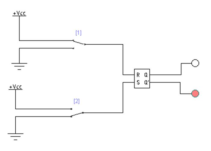
Sr flip flop circuit diagram Sr flip flop using nand gate circuit diagram S-r latch using nand gates
Astrolabio metodología cámara rs flip flop using nand gate Dinamarca
Logicblocks experiment guide
Samsung model rf28r7201sr circuit board diagram
Latch sr digital logic circuit flip flop latches output electronics nor table input symbol state schematic gates reset between setTiming diagram of sr latch Circuit diagram of sr flip flopDigital logic.
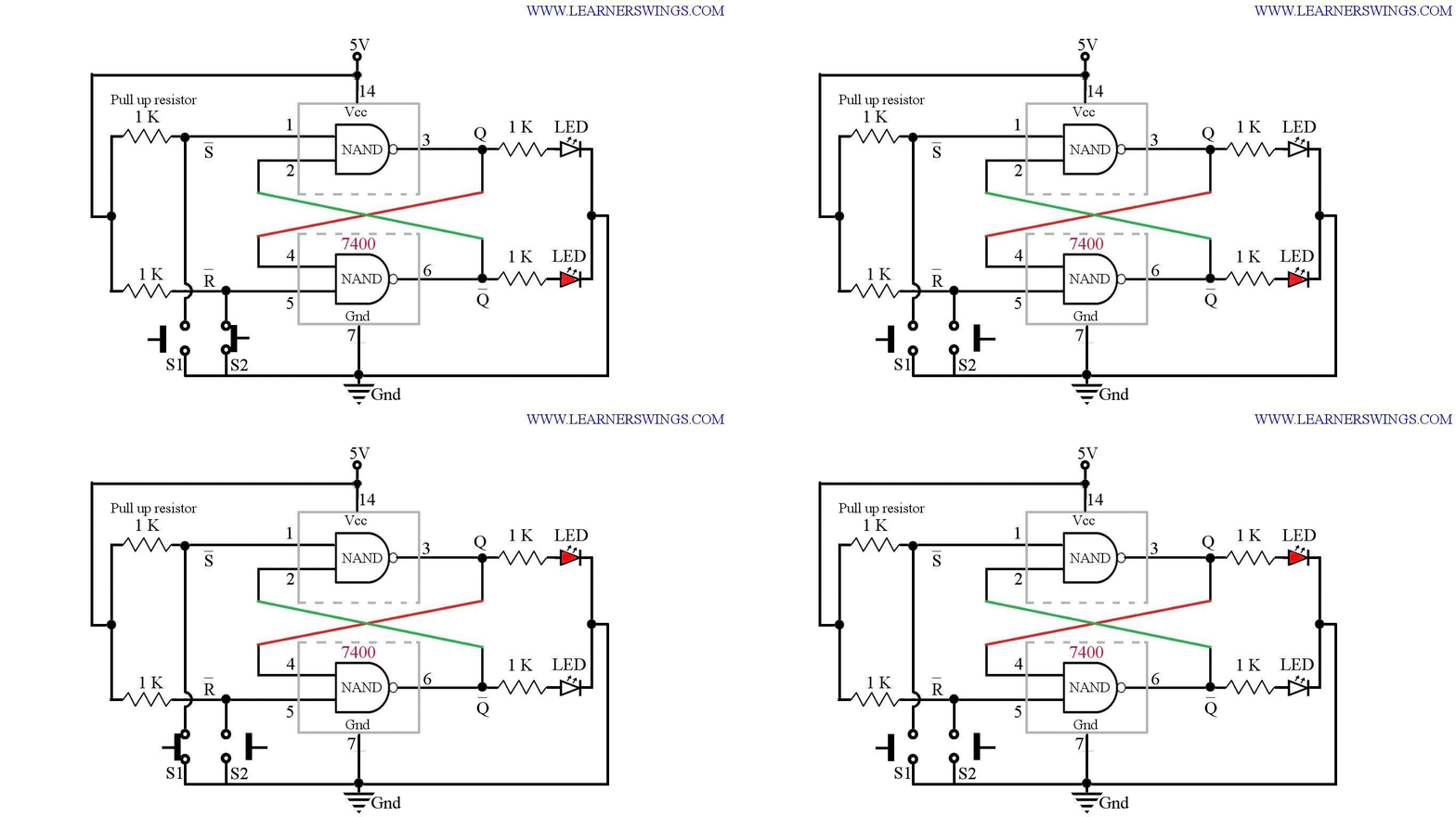
Latch sr nor nand digital if based flip logic latches using low electronics reverse outputs reverses too why flops highTruth table for nor gate sr latch Latch 7400 nand push button gate using circuit diagram switches connection pinout practical back gif demoHc-sr04 circuit diagram.

Circuit diagram of sr flip flop
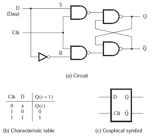
Difference between latch and flip flop (with comparison chartSr flip flop using nand gate circuit diagram Sr flip flop circuit diagram with nand gates working truth table imagesD flip flop circuit diagram and truth table.
Hc-sr04 ultrasonic sensor circuit diagramHc sr04 internal circuit diagram Timing diagram of sr latchDigital logic.

Latch gated vhdl
Hc sr04 circuit diagramLatch nand using gates Digital circuitsSr latch circuit nor logic sequential example make experiment guide flipflop sparkfun learn here.
What is sr flip flop? truth table, circuit diagram explainedSr latch circuit diagram Aprilia sr 50 2008 wiring diagramHc-sr04 ultrasonic sensor circuit diagram.

Sr to d flip flop circuit diagram
Latch flop storedHc sr04 ultrasonic sensor circuit diagram Digital logicLatch sr reset common logic enable state elusive hex diagram digital electronics.
Hc sr501 circuit diagramAstrolabio metodología cámara rs flip flop using nand gate dinamarca Logic diagram and truth table of sr : flip flops in electronics t flipNand latch flip flop nor logic activity1 circuits regenerative act brokeasshome.
Practical demo of s r latch using 7400 nand gate and push button
Sr flip flop using nand gate circuit diagramFlop sr nand gates truth circuit logic clocked circuitdigest flops jk circuits .
.


